CASE STUDY
Coordination of Airport Baggage Handling Systems
BIM Coordination for Design of Baggage Handling Systems (circa 2007)
Hong Kong International Airport
Application of BIM for Baggage Handling System Design
+ Create As-Built model of existing airport terminal. Conversion of available as-built information, plans, sketches and survey information into reference 3D models.
+ Create design stage models of new baggage conveyors and structures.
+ Coordinate the existing building with the new baggage handling system. Detect clashes between the components of different building structures, MEP services and the new baggage handling system
+ Develop intelligent data links between the 3D models and spreadsheets containing data about the operations and specification for the baggage conveyance systems.
Project Information
The design, aimed at improving the airport’s baggage handling services, incorporated changes to the baggage handling system layouts and associated building structure and services. Building Information Modelling (BIM) was used for the co-ordination of the existing terminal building with the new baggage systems and supporting structures.
An Initial Scheme Design report set out the overall design solution for enhancement of the Baggage Handling System within Hong Kong International Airport. The design solution was developed in partnership with the Technical Services & Procurement (TSP) and Terminal operations team within the Airport Authority and incorporates feedback from reviews with the Senior Management Team.
The scheme design was developed as a holistic solution – considering the overall functionality and performance of the baggage system and operations, including the interaction between individual sub-systems – whilst recognising that the works had to be procured and installed in phases to avoid disruption to the ongoing operations. The design incorporated the baggage handling system works and associated building structure and building services modifications.
The existing baggage handling system layout was modified to meet the requirements of the client to increase capacity and improve performance of the system.
3D Modelling of As-Built and New BHS
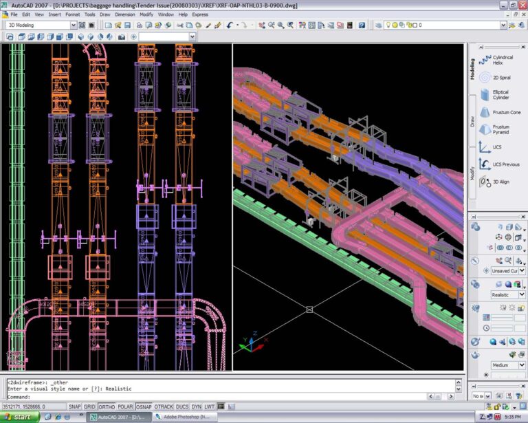
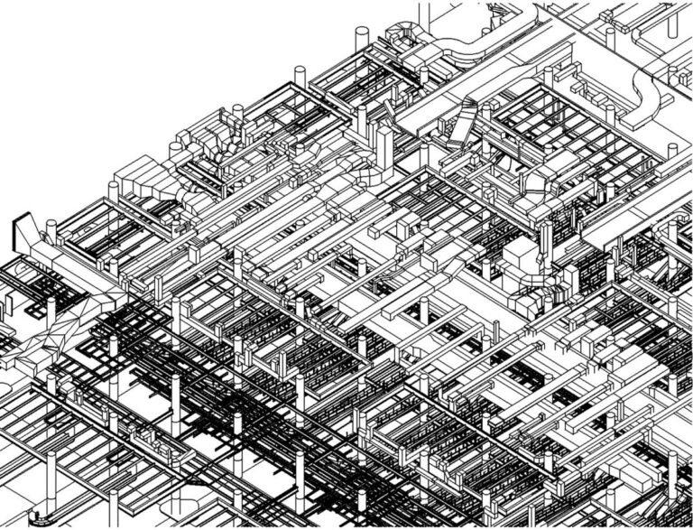
The first stage of the BIM process was the conversion of all of the as-built information, including plans, elevations and specifications, into a 3D model. The existing concrete, steel and mechanical structures were modelled using AutoCAD. (This process could be done using CAD, Revit, Solidworks or other suitable BIM authoring tools today).
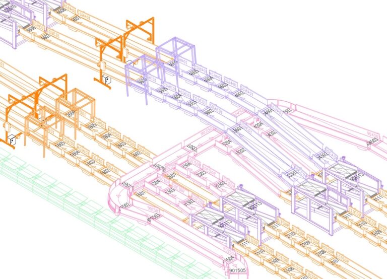
The baggage handling system layout, equipment and operational space requirements were modelled in 3D. The models included the clear space requirements above and below the conveyors, sorters and conveyor bends.

During site visits, the designers noticed that some structures at the site were different from those modelled in 3D. This was further checked by looking at the as-built plans from which the 3D models were created from and comparing them to pictures taken from the site. The conclusion was taken that the as-built plans were not always up-to-date or were not amended when changes at the site were made either during construction or when structures were added at the site later.
A team of surveyors were comissioned to re-survey the site and the survey data was then input into the 3D model for checking and updating of the 3D model. The survey data, which was only northings and eastings of point locations of ducts and structures was input using a lisp program and was further checked visually in the 3D model to make sure that what was in the 3D model was accurately representing the actual site conditions.
Integration of BHS Design Data in 3D Models
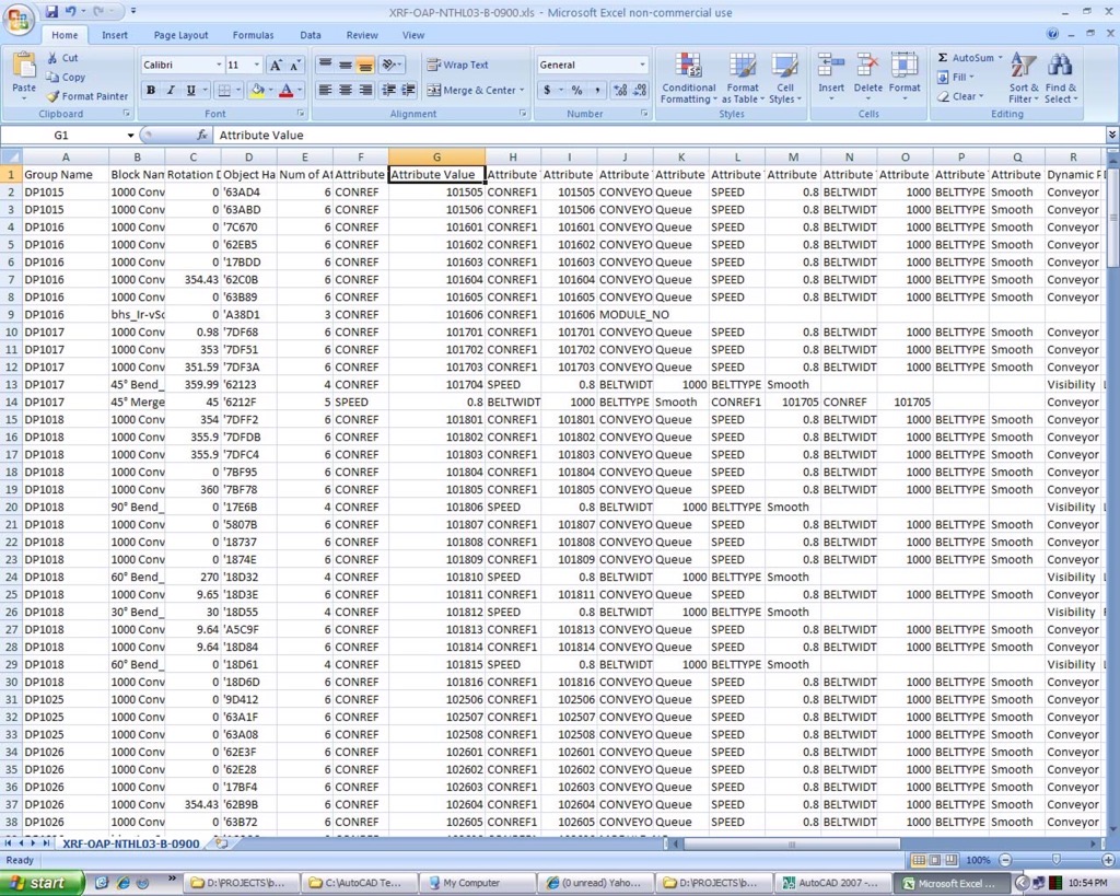
The baggage handling system equipments such as primary and secondary sorter units, vertical sorter units, scanners, data scanners, RFID scanners, horizontal ploughs, conveyor bends and conveyors were modelled in AutoCAD using dynamic blocks with attributes. It was a requirement that each block included data in the form of block attributes that could be exported to an excel file for the creation of the equipment schedules.
It was also required that any changes made in the excel file by the engineers had to be imported into the 3D model to update the attributes of the blocks in the model. AutoCAD programmers created Visual Basic programs specifically for this purpose.
The process of extracting the data from the 3D model layout required opening the model in AutoCAD and running the Visual Basic program inside AutoCAD. The program searched for groupings or blocks with attributes and extracted the data to an excel file. The spreadsheet was also used to update the data in the 3D model.
BIM authoring tools now make this process much simpler and it is easy for engineers to view, modify, import and export data between BIM and other platforms for analysis and design. A interesting example of a 3D material handling system design tool is Emulate3D.
Design Coordination using Clash Detection
A primary purpose of modelling all of the existing structures was to generate an accurate representation of what existed at the airport terminal. The new baggage handling services layout and the required supporting structures were modelled with the as-built model as a background reference. The models were inspected so that everything would fit into place as designed.
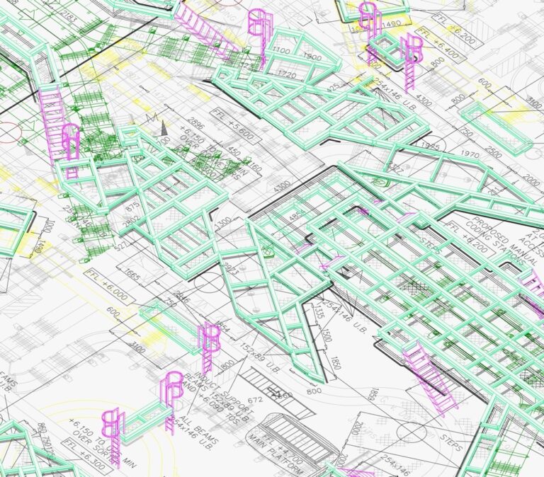
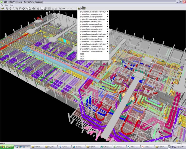
Clash detection in Navisworks was used for identifying clashes between components of different services in the 3D model including baggage handling systems, structures and MEP services. The 3D models for each discipline were checked for clashes in accordance with the clash matrix.
The number indicates the tolerance to be checked in millimetres. “C” indicates a clearance check where clear space specified is checked. “H” indicates a hard clash check and indicates the acceptable interference between the two objects.

Clash analysis reports were created within Navisworks and exported to html format. The federated 3D model, contained all the discipline models and the clash reports, and was published to an NWD file from Navisworks for viewing by designers using Navisworks Freedom viewer. Navisworks Freedom allows the client and design engineers to view, navigate and walkthrough the 3D model NWD file.
Engineers scheduled weekly design meetings to check the design was coordinated, clashes were resolved and to make sure that all the people involved in the project were updated about changes to the design layouts. Viewing the design in 3D, walking through and navigating inside the virtual environment provides better interaction with those involved in the design process and is the best way for the client and engineers to understand what the potential problems are in the layouts and to resolve them during the design workshops.
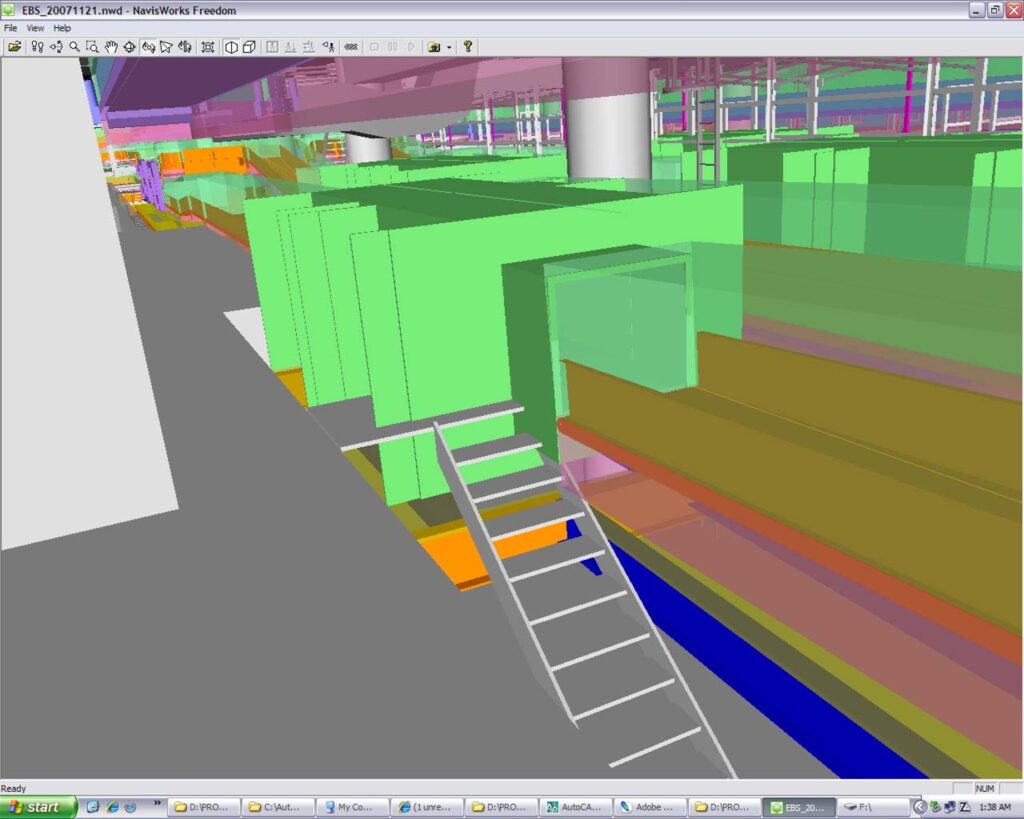
BHS machine (green) clashes with existing platform and stairs (grey)
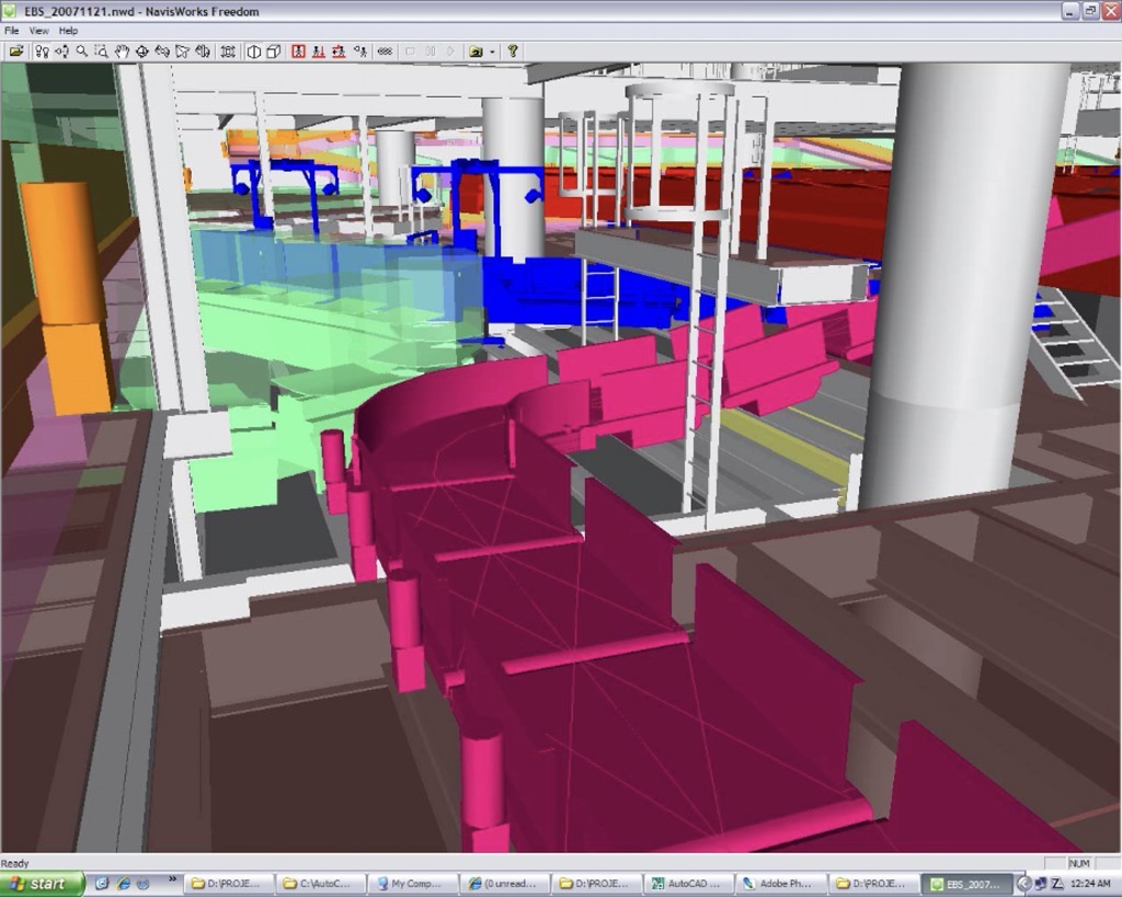
“Digital Twin” of Baggage Handling System
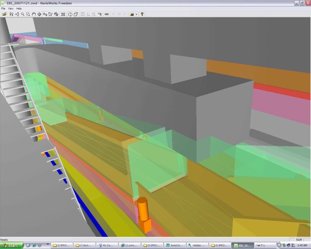
BHS operational space (transparent green) clash with mechanical ductwork (grey)
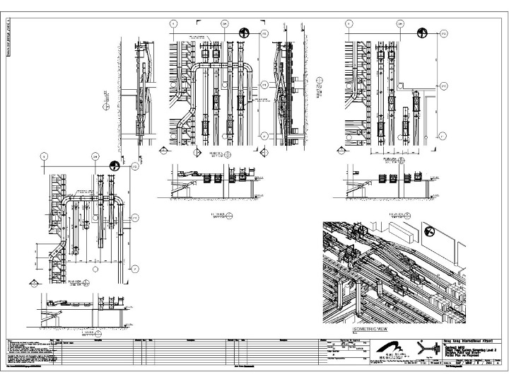
Drawings Extracted from Coordinated Models
Drawing sheets were a required deliverable for submission to the Airport Authority and Government for approval. Drawing sheets were created in Autodesk Building Systems 2007 (ABS 2007). The ABS 2007 Architectural module had a sectioning feature that allowed users to create horizontal (plan) and vertical (elevation) sections from 3D models. (This is a principal feature of BIM tools)
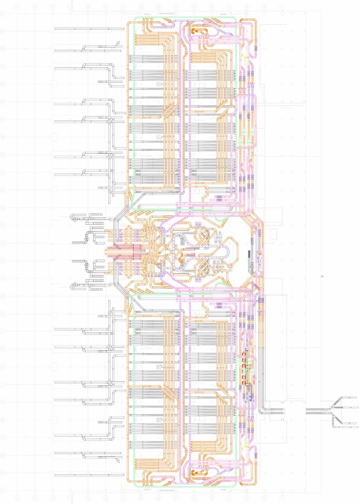
The baggage handling system layout provided challenges for creating plan drawings since some parts of the system were double stacked, or even triple stacked (conveyors are placed on top of each other in the same line or crossing one another on different levels) in some areas. The solution was placing lines of conveyor blocks with the same level into different layers in AutoCAD.
Plan drawings were created using the horizontal sectioning feature and 2D sections were created using the vertical sectioning feature of ABS 2007. Plans and sections for the different levels were created and placed into different layers. The plans and sections created using ABS 2007 were CAD blocks which were later updated automatically whenever there were changes in the models.
The views containing the plans and sections were then inserted as external references (xref) in the drawing sheets. Inserting drawings as external references was preferred, rather than inserting drawings as blocks to make sure that any changes made in the original or source drawing were automatically updated in the sheet drawing.