CASE STUDY
Hong Kong Convention and Exhibition Centre
How was 4D used in 2006 for the convention centre in Hong Kong and what would we do differently today
Project Information
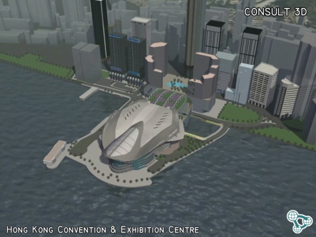
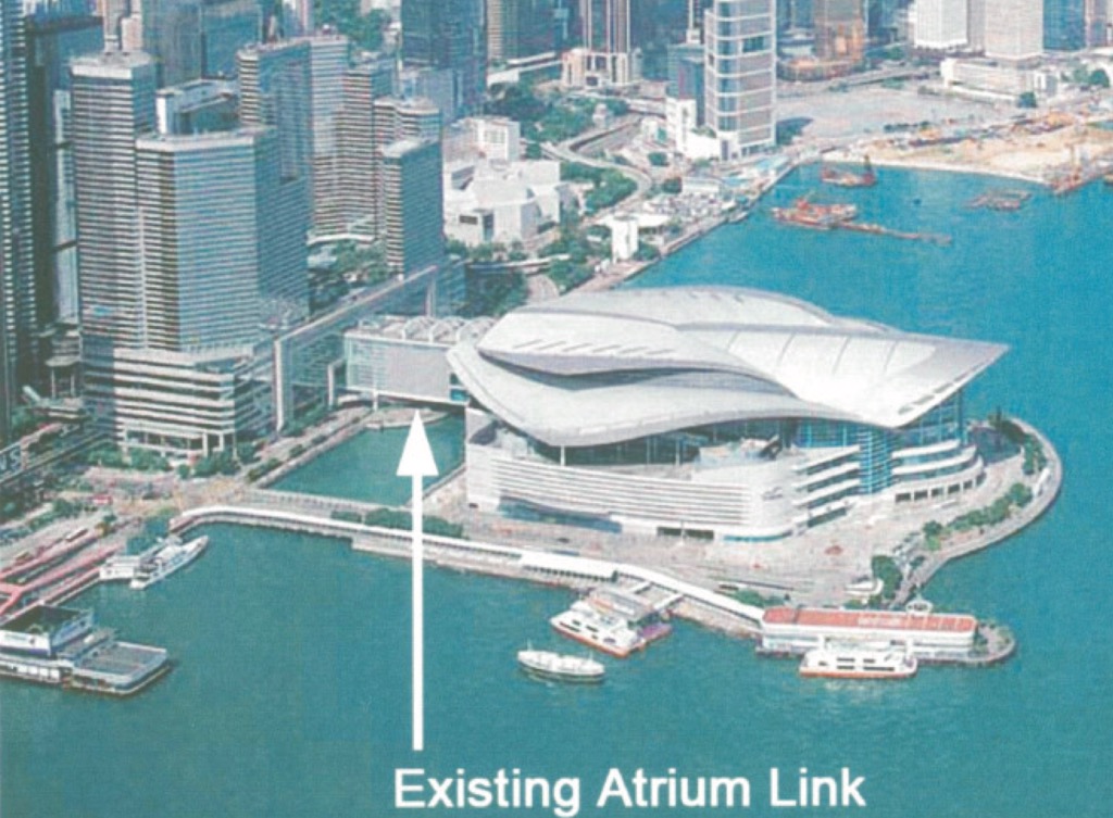
The original exhibition centre (phase one) was built in 1988. The glass curtain wall was the world’s largest at the time, overlooking Victoria Harbour. The second phase of the centre, located on a reclaimed island, was constructed from 1994 to 1997. The project took only 48 months from reclamation to completion. Phase two was originally connected to phase one with an atrium link sky bridge.
In 2006, HKCEC invested HK$1.4 billion (USD 180m) to construct 19,400 square metres of additional exhibition hall space. The sky bridge was replaced with these expanded halls, bringing the total exhibition space to nearly 83,000 square metres (900,000 sq.ft).
The extension spanned across a waterway and consists of three main levels. There were no columns allowed for in the waterway and no reclamation was necessary. For more information on the planned construction activities refer to the environmental report.
(In later years, the waterway was reclaimed and is part of the road alignment for the Central Wanchai Bypass and new MTR tunnels.)
Why was 4D used?
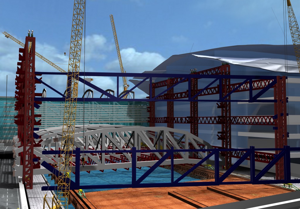
At the tender stage, the China State – Leighton joint venture team developed a number of innovative solutions for the erection of this complicated steel structure. As part of their tender submission and to improve engagement with the client, they procured a 4D model.
The purpose of the 4D sequence was to communicate the contractors’ intent clearly in order to demonstrate to the client that they fully understood the complex project and they had developed robust engineering solutions to build the super structure.
What was produced using 4D?
The contractor commissioned a 4D animation and method statement images to illustrate their planned methods and sequences. The animations and images were used to demonstrate the construction methods for 3 critical areas of work.
- Maintaining public access to the exhibition halls during construction
- Relocation of the sky bridge to the west
- Erection of the new exhibition hall structure to the east
This case study is focused on the primary structure erection sequence. The original video with narration is available here
How was 4D implemented?
As this project was in 2006, in the very early days of “BIM” adoption, there were no models available from the design consultants. The tender was procured using traditional architectural and engineering drawings. The 3D models for the new structural steel were generated by a structural engineer in CAD as solid models and imported into the 4D software.
In order to give the presentation the important context of being located between phase one and phase two of the HKCEC, the animation team created background models of the existing buildings, roads and surrounding harbour. These shells were produced by referring to the architects plans and elevations for the existing complex.
The contractors team developed their concepts and ideas during the early stages of the tender period. China Station and Leighton engaged with Freyssinet to develop methods for the, temporary works, heavy lifting and erection of the long span steel structures.
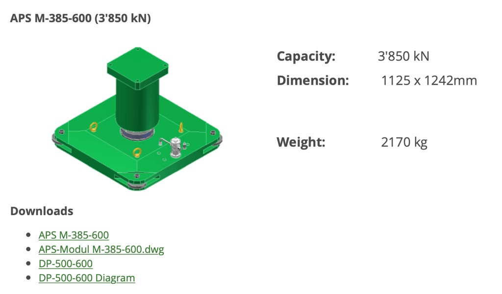
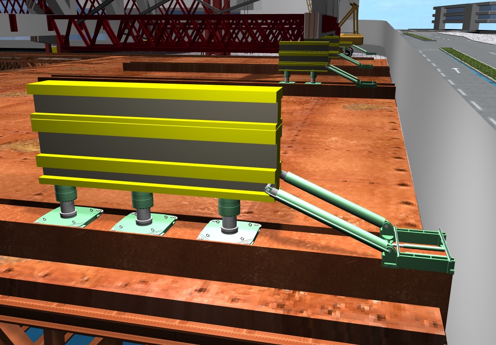
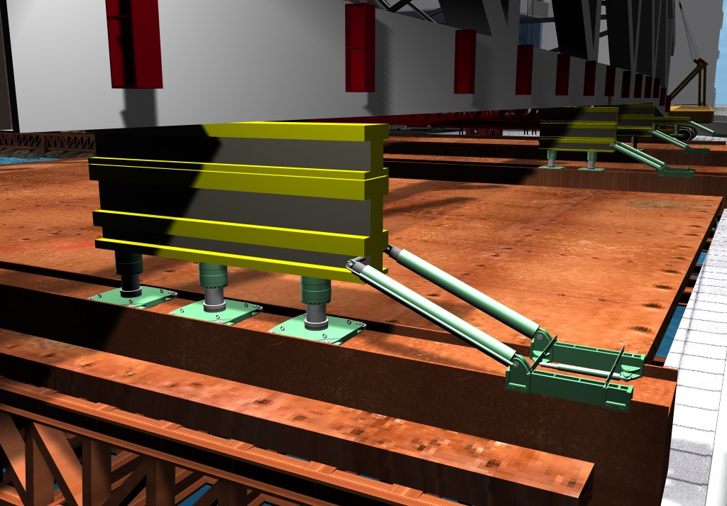
The engineers chose to use an Air Pad System and 300 ton strand jacks from Hebetec. The air pad system consists of jacks which can raise or lower the steel. Using air pressure to lift the steelwork, the APS uses push/pull jacks to move the steel laterally along sliding rails.
As there were CAD files available for these specialised systems, the 4D team were able to quickly generate 3D models for inclusion in the simulations. You can still download the DWG files from the Hebetec Engineering website here
The remaining heavy machinery including cranes, barges and working platforms were taken from existing model libraries or were modelled from suppliers information.
The 4D team engaged with the contractors engineers and planners to discuss, understand and develop the 4D simulations to reflect the details for the innovations described in the method statements. In some cases, the 3D models were used by the engineers to review different options for the erection sequence and to validate their decisions on the planned sequence of works.
The contractors schedule, in the form of a Gantt chart was used as reference for the timing of the works. However, the dates for the activities were not linked to the 3D models.
Throughout the tender period, the models, sequences and overall presentation were amended and improved, with a focus on clearly illustrating the innovative ideas developed by the engineers. Numerous images were included in the contractors tender submission documents.
The final animation was provided to the client on a CD as part of an executive summary by the China State Leighton JV. Unfortunately the contractor was not successful for this tender.
Today’s version of 4D
How does this case study relate to the latest practices and what would be done differently today. The skills required to create the 4D simulation haven’t changed.
Here are the processes and tools a team of engineers, planners and subcontractors could use today.
+ The 3D structural model should be available from the design engineer. Ideally as a Revit or Tekla model or as an IFC model.
+ The architects are likely to have good background models for the surroundings from their design visualization process. These could be shared with the contractors.
+ An alternative process would be to use cameras and drones to survey the current building to generate a 3D model of the site location using photogrammetry.
+ For the tender period, it’s likely that the models could be linked to a P6 schedule or Gantt Chart for the primary structural works. This may involve the planners and modellers agreeing on a parameter naming convention or a basic work breakdown structure to semi-automate the linking of the programme information to the models. It’s not entirely necessary.

+ By creating the 4D sequence in Synchro, Navisworks or a similar tool, this will make it simpler to arrange team planning workshops and discussions to review and update the programme, models and 4D simulations. The 4D models can now be more easily shared and reviewed by larger project teams.
+ Synchro and Navisworks can produce good quality images and animations for tender submissions. Of course, they can also be used for a lot more than simply bidding for work.
+ Experienced 4D teams will continue to use the 4D BIM process after contract award. More and more planners are now able to manage the updates to the information in 4D and are finding ways to integrate progress updates from site to their P6 schedules and into the models. This is a powerful way to monitor progress and find opportunities to save time on projects.
4D Images for Method Statements
working platform over channel
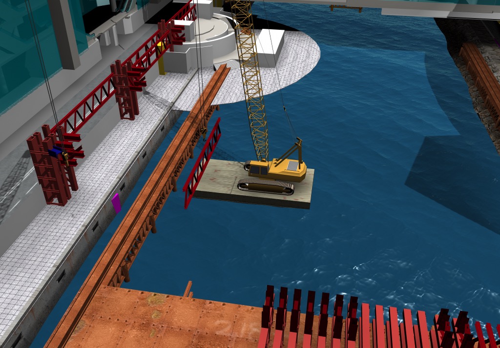
2-crane on barge
Steel Erection Innovations
B2_fr_2_air_pads
B3_fr_1014_TB3
B4_fr_1400_ajust_airpads
B6_fr_1955_slide_trusses
B7_fr_2649_final_lift_position
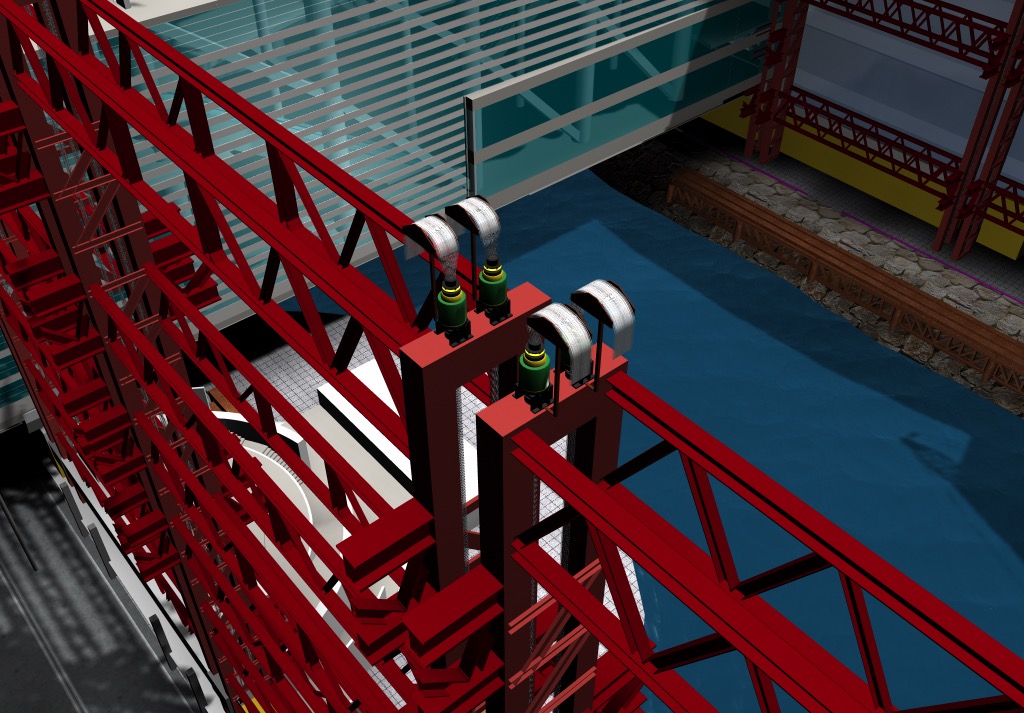
Hebetect 300 ton strand jacks
C6_fr_3075
C7_fr_3199_install_C5
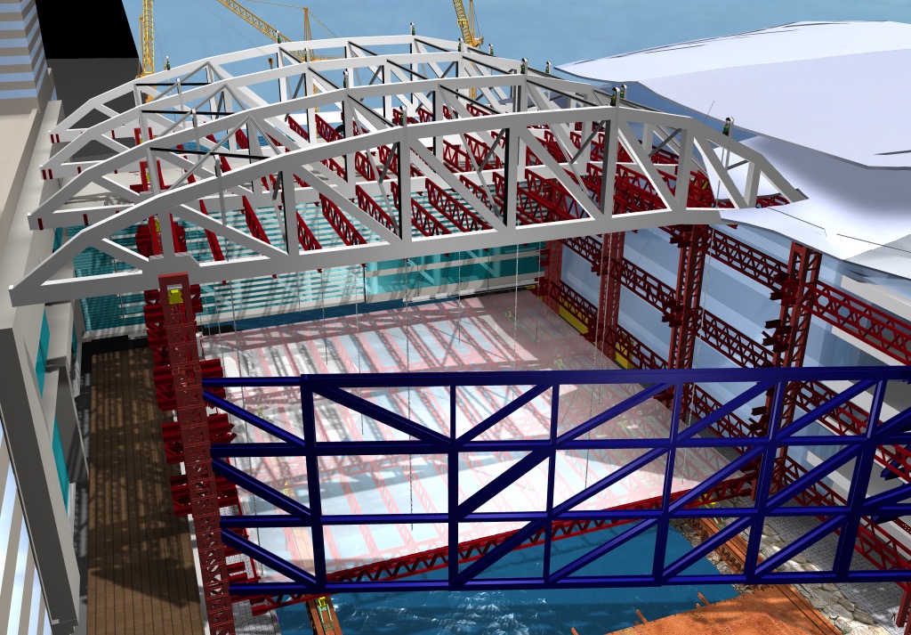
Roof Truss Final Position
D2_fr_2700_Truss_E_delivert
East Truss Assembly
E4_fr_4132_slide_27m
Exhibition Hall Floor Structure
F1_fr_4485_Lifting_plate
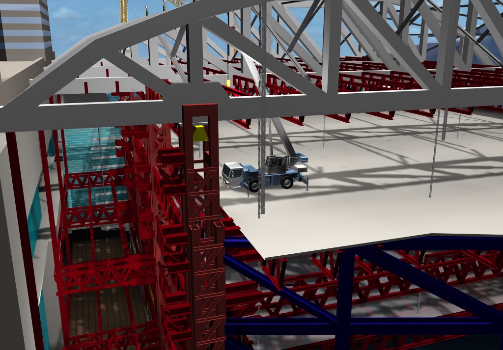
Mobile Crane Installed on Deck
Structural floor plate hoisted to final position by strand jacks
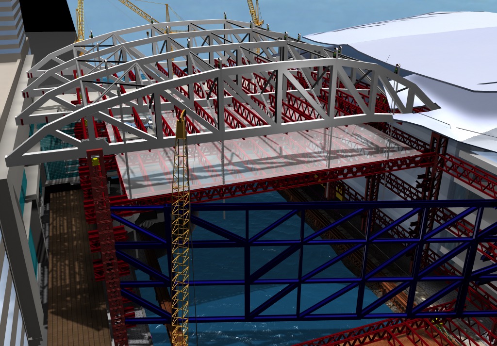
Assembled structural floor plate ready for lifting by strand jacks
Why 4D
- Communicate the contractors’ plan clearly
- Demonstrate comprehension of the complex issues
- Illustrate innovative ideas using systems from other industries
4D Outcomes
- 4D animations
- 4D sequence images
4D Process
- 3D solid models of steel & concrete structure generated in CAD from 2D tender drawings
- 3D models of surroundings & background generated from architects drawings
- Sequences were key-framed in Maya animation software based on contractor gantt charts
- Animations & Images were rendered from Maya
Limitations
- Design models were not available
- Steel fabricators models were not available
- Schedule (programme) was not linked/connected to 3D models
- Animations were for tender purposes only
4D Skills
- 3D modelling (buildings, temp works, heavy machinery)
- Construction planning (scheduling)
- Presentation & communication (story telling)
Cast Study References
HKCEC business view of the expansion project
Environmental Impact Assessment
Strand Jacks by Freyssinet
Western Kowloon | Bridge Erection | Lowering
Platform NR2 in Korea moved by Hebetec
Oil Platform Mars B launching with APS
Original 4D Video Narration
The original animation script is included below for reference.
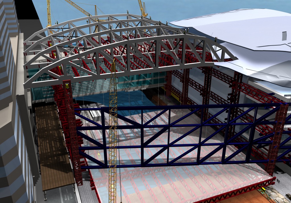
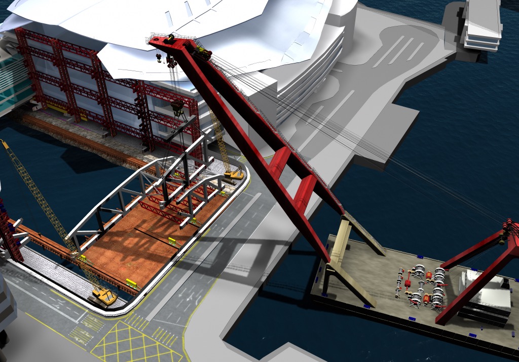
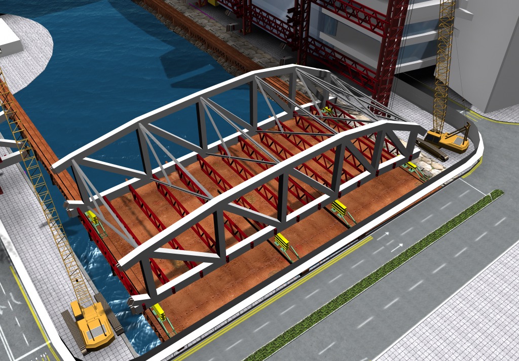
The China State – Leighton joint venture team developed a number of innovative solutions for the erection of this complicated steel structure. The main working area, a temporary platform had two sliding rails along the North and South sides of the site. The plan was to erect mega column sections in pairs of pre-fabricated box sections with the stubs for the primary floor trusses attached.
The China State – Leighton joint venture team developed a number of innovative solutions for the erection of this complicated steel structure. The main working area, a temporary platform had two sliding rails along the North and South sides of the site. The plan was to erect mega column sections in pairs of pre-fabricated box sections with the stubs for the primary floor trusses attached.
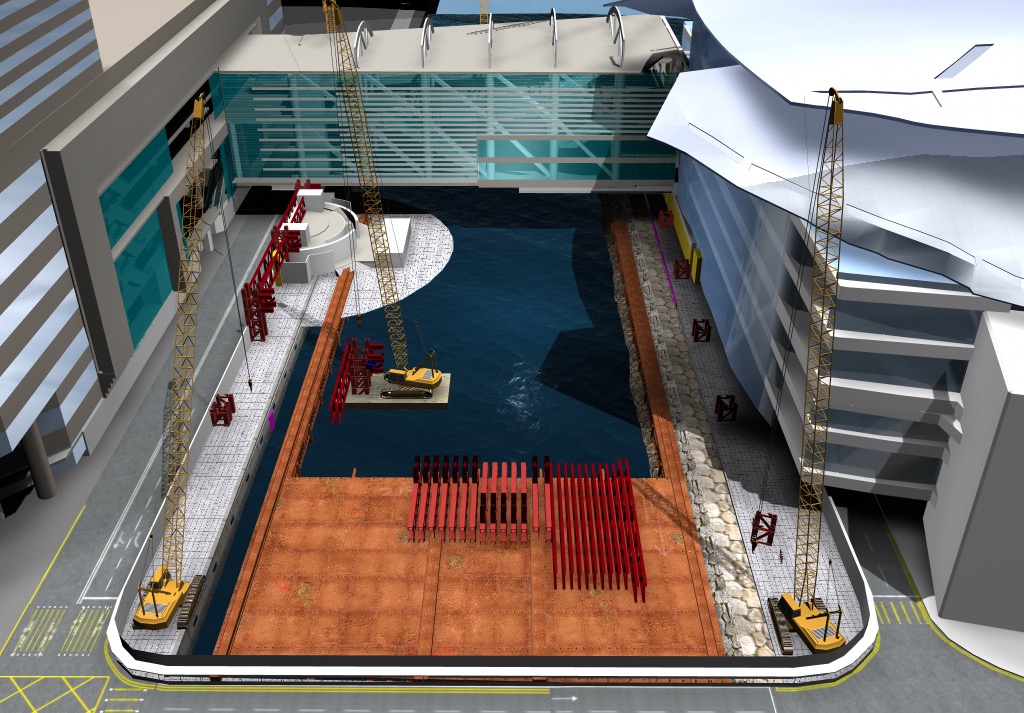
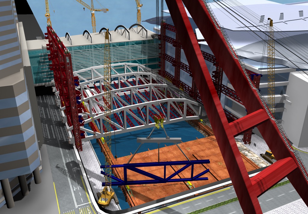
Two shore based mobile cranes and an additional crane on a barge within the site were to be used to assemble and erect the steel mega column sections.
All of the column sections would be erected by the crane from within the site. The steel erection commenced when the pile caps for the mega columns were completed.
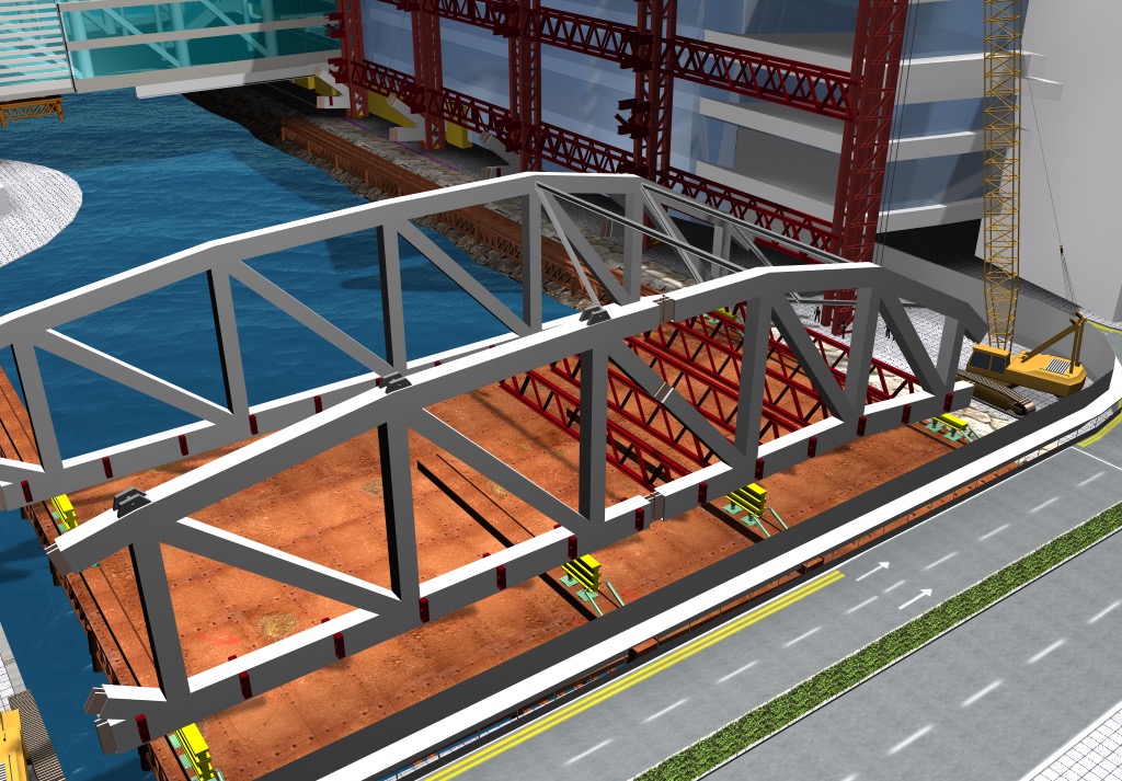
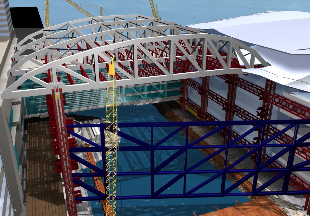
Four 300 ton strand Jacks were to be installed on cross-head beams at the top of each mega column. The type 4 roof truss, end sections, were installed with a lifting Beam at the base of the south columns. The type 1 truss end sections were installed with a lifting Beam at the base of the north columns.
The large roof truss sections, prefabricated in China, would be delivered to Hong Kong by large barges. The plan was to use a marine crane to lift each 900 ton truss section onto the working platform area. The heavy lifts would take place between midnight and 6 am.
Expo Drive East would be closed for each heavy steel lift while Convention Avenue would remain open to traffic at all times.
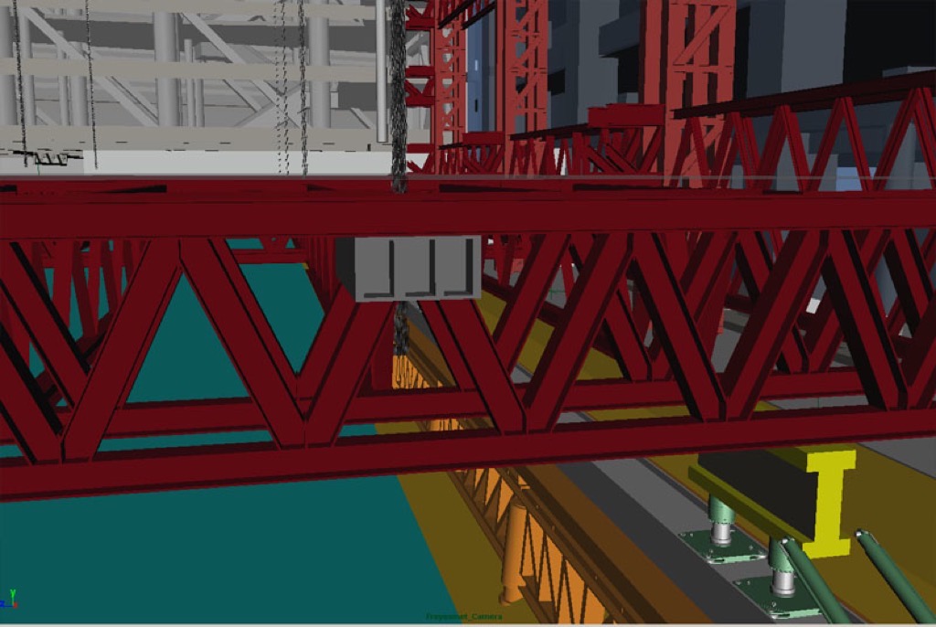
Each truss section will be supported by the Hebetec air pad system. The jacks can raise or lower the steel. Using air pressure to lift the steelwork, the APS can be used to push the steel laterally along the sliding rails.
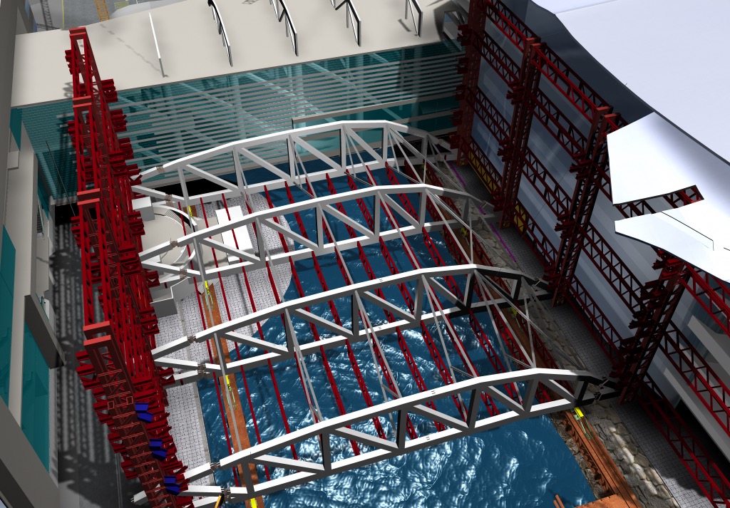
The air pad system provides a powerful levelling bed for positioning and connecting the roof trusses. Each truss can be accurately and safely assembled. When the truss sections are level and square, they will slide together on the air pads the central plates of the truss will be bolted and then welded together on site. The external splice plates will be connected with full penetration, butt Welds.
The secondary roof trusses and tertiary roof beams could be installed between the primary trusses by the land-based cranes. The air pad system elevates the steel assembly on a cushion of pressurized air. The floating structure could then be pushed 27 meters along the sliding rails by the push-pull jacks.
The remaining primary roof trusses and other secondary steelwork would be erected in the same way until all of the roof sections are assembled. The complete structure can be pushed to the final lifting position on the air pad system by the push-pull jacks. The end sections along the north and south sides could then be connected to the main roof trusses.
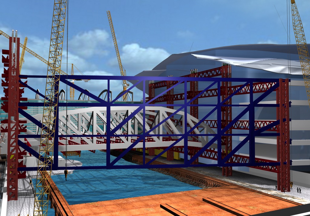
The longer span, east elevation truss would be delivered onto the working platform in four separate sections by the marine crane. After splicing the trusses together, they would be lifted into their final position using strand jacks. The intermediate posts and diagonals will then be installed to complete the long span truss.
To install the final cantilever roof sections above convention avenue in a safe manner the roof steel will be raised approximately 10 meters above the road. The final truss segments could be installed by a mobile crane during a night time road closure for each of the four truss sections. The roof steelwork will then be lifted to the final level using the strand jacks and safely secured on permanent beams.
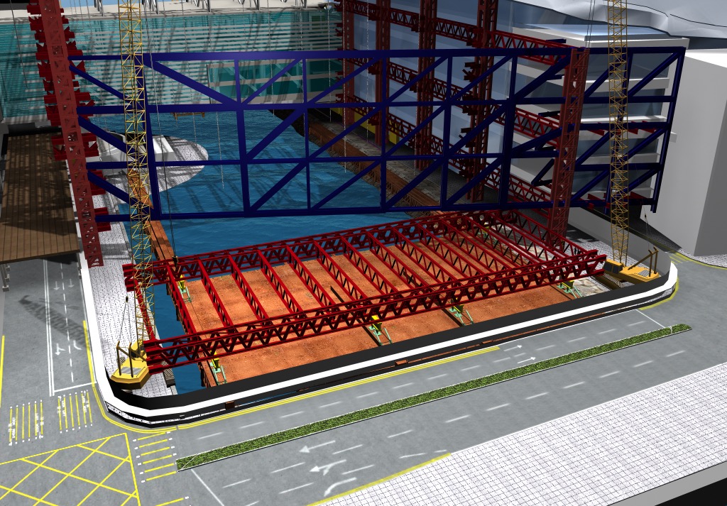
The levelling bed, air pad system and push-pull jacks could be re-used to assemble each of the long span exhibition structural floors. As each 27 meter bay of the floor is completed the bondek, shear studs and reinforcement will be installed at the safer lower working levels.
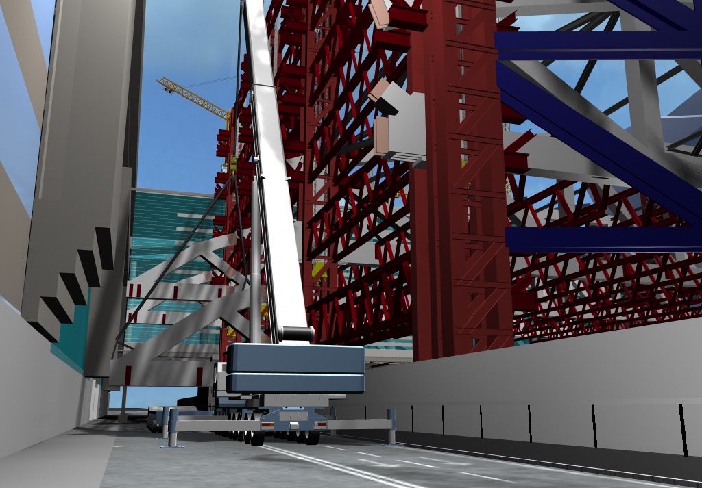
Mobile cranes could be placed on areas of concrete floor deck and they would be used to install steelwork for the intermediate floors.
The primary floor trusses would be raised at four hoisting points by strand jacks installed in the primary roof trusses. The steel truss connections were detailed to provide maximum clearance during the lifting operations. The structural floor trusses needed to be connected to the mega columns before the composite concrete slab could be cast. As each floor was completed and lifted into position, the next lower floor could be assembled on the air pad system and levelling platform.
The floor framing above Convention Avenue could be constructed by mobile cranes from Level 7 in a traditional bottom-up erection sequence using a crash deck over the road for safety.
On the successful completion of the erection of the primary steel structure the construction methods would then revert to traditional commercial building type works.